Showing posts with label arduino. Show all posts

Wednesday, April 27, 2022

Updating the Kernelcon 2022 Badge Wifi

So you got home, powered up your Kernelcon 2022 badge, and discovered that it won't boot without the conference wifi network?  It took me a little bit, but I finally figured out how to reflash the thing with new wifi settings.  Turns out you just need to teach an Arduino IDE to talk to an ESP 8266 board, and you can upload the code with new wifi settings easily.

Let's do the Arduino set-up first:

  1. Download and install the Arduino IDE
  2. Open it up and go to File > Preferences
  3. In "Additional Boards Manager URLs" add
    https://arduino.esp8266.com/stable/package_esp8266com_index.json
  4. Hit "OK"
  5. Go to Tools > Board: ____ > Boards Manager
  6. For "Filter your search" type "ESP8266" and let it find the module
  7. Click "Install" and it should download and install the add-on
  8. Click "Close" when that's done
  9. Select Tools > Board: ____ > ESP8266 Boards > Generic ESP8266 Module
  10. Select Tools > Flash size: ____ > 4MB (FS:1MB OTA:~1019KB)
  11. Plug in your badge and switch it on
  12. Go to Tools > Port and select the port it's on.  (Kali picked /dev/ttyUSB0)

At this point, you can load whatever Arduino code you like.  The official Kernelcon badge code uses a JSON library, so if you're going to reload the official code, install the JSON library first.

  1. In the IDE select Tools > Manage Libraries
  2. Search for "ArduinoJson" and click "Install" to add it
  3. Click "Close" when it's done installing.

Finally, let's fetch the original badge code, update the wifi settings, and upload it to the badge.

  1. Download and unzip the ZonkSec kernelcon-2022-badge code
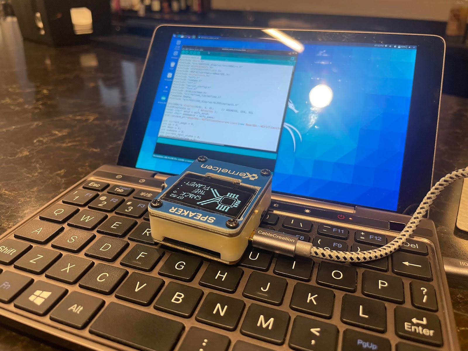
  2. In the Arduino IDE, open kernelcon_watch_v4.ino
  3. This opens all the source files.  Select the wifi.h file tab
  4. Update the SSID and password values and save the file
  5. Select Sketch > Upload and watch it compile and transfer
  6. The badge will restart, and it should use your updated wifi settings as it does.

That's it!  Mess around with the badge code some more, if you like.  Or go find some ESP8266 code and mess with the little guy.  For me, my next step is to try to get the original deauther code running.

Sunday, February 3, 2013

Glove Parts

My friend Erica challenged me on my birthday.  She sent me three Lilypad pieces -- an RGB LED, an accelerometer, and an electret microphone.  The "challenge" part is that she packed them inside a CD jewel case .. with my face photoshopped onto Imogen Heap showing off her gloves.

I've already got an old mainboard, and a bunch of conductive thread.  I picked up a cheap pair of fabric gloves while I was running an errand on Friday.  I'm going to sew this stuff together and see what it might like to be when it grows up.

Thursday, February 9, 2012

OLED Screen is Operational

I got my new OLED screen to run the example code.  To draw my own bitmaps, I'll need an app that can convert a monochrome bmp into a character array.  So far, there's only a windows app to do the conversion ... though I wonder if ImageMagick can do it.

This display is for my robotics class.  Since my robot needs to be autonomous, printing debug information to the USB port isn't gonna work.  (At least, not for more than a couple meters, when the cable slack runs out.)  I'll attach this guy to the robot and print debug messages to it.

Wednesday, January 25, 2012

Setting up FTDI (for XBee) on Mac OS X

My awesome brother and I have been playing with XBee radios for the past few days.  Darned near all of the programming interfaces -- and fancier breakout boards -- use a USB-to-FTDI serial translator.  I've got a new Air here that doesn't have the drivers installed yet.  So, since it took a minute or two to determine what I needed, here's my quick outline for the next time:
  • You want the Virtual Comm Port (VCP) version of the driver.
  • Plug in.  See if Terminal.app shows the new cu and tty devices, with `ls -l /dev/*usbserial*`
  • CoolTerm seems to be a nice terminal emulator.  (ZTerm still works, for the old-skoolers!)
  • Plug in USB .. to FTDI translator .. to breakout board .. to XBee radio.
  • XBees ship with 8N1 serial at 9600 baud.  Set your terminal emulator accordingly.
    • XBees don't echo your input, so turn on Local Echo in your terminal emulator.
  • In the terminal emulator, type "+++" to get into command mode.  XBee will reply "OK."
  • Continue building your robot army.
You don't actually need CoolTerm or ZTerm, if you don't mind that `screen` won't do a local echo.  If you're okay with typing blind, a `screen /dev/cu.usbserial*` command should work just fine (as long there's only one usbserial device connected at a time).  Crafting a one-liner that fakes local echo is left as an exercise for our new robotic overlords.

Saturday, January 14, 2012

DS18B20 Temperature Sensor on Arduino

I just got a DS18B20 temperature sensor from adafruit, and it took a little sleuthing to get it working.  There are a few sources of sample code, but none of them tell you how to wire the silly thing in the first place.  I eventually got it.

I downloaded and installed the Dallas Temperature Control Library, then I used tushev's wiring diagram to hook it up to an Arduino Uno.  The "Tester" example that's included with the library confirmed that everything was in one piece.  Hopefully that helps, if you're in the same boat..

Sunday, January 1, 2012

Using RGB LEDs on an Arduino

Click to embiggen.
For some reason, it wasn't easy to find sample code or pinouts for using a common-cathode RGB LED with Arduino.  I think I'm missing something obvious, but oh well.  So, I messed around and got it to work.

  • The longest pin takes 5v in.
  • Grounding the other three illuminate red, blue and green.
  • You can use digital PWM outputs to ground those pins.
  • Setting a pin to 0 illuminates that color.  1023, off.
  • Setting a pin to an intermediate value adjusts its brightness.
I've done a super simple diagram, at right.  And copypasted some bare-bones code that runs through each pin, in turn, grounding it for a half second.  These links go directly to the sketch, and the fritzing diagram.


//
// RGB LED figure-er-out-er by gabe.                 gms@causalloop.com
//    an Arduino & Beer (tm) Production.                blog.fnaard.com
//
// Run your RGB LED's longest pin to 5v.  Run the other pins to digital
// pins 9, 10 and 11.  I've put a 330 ohm resistor, in series, between
// each of those three pins and its corresponding digital pin.
//
// This sketch runs through pins 9, 10, 11 grounding each one in turn ..
// for sussing out which pin illuminates which color inside the thing.
//
// You gotta set all the pins to OUTPUT, so that you can write values
// to them.  They won't actually output any voltage .. in fact, they'll
// act as ground.  Setting a value for the pin will adjust its PWM rate
// and that adjusts how much electricity can flow through that color LED.
//
// Put simply, it's what you do with single-color LEDs, but in reverse.


void setup () {
  pinMode ( 11, OUTPUT );
  pinMode ( 10, OUTPUT );
  pinMode (  9, OUTPUT );
}


// Now just run through the pins, setting each one to full brightness (0)
// for a half second, while setting the other two to off (255).


void loop () {
  analogWrite ( 11, 255 );
  analogWrite ( 10, 255 );
  analogWrite (  9, 0    );        // Red, on mine.
  delay(500);
  analogWrite ( 11, 255 );
  analogWrite ( 10, 0    );
  analogWrite (  9, 255 );     // Green on mine.
  delay(500);
  analogWrite ( 11, 0    );
  analogWrite ( 10, 255 );
  analogWrite (  9, 255 );     // Blue on mine.
  delay(500);
  analogWrite ( 11, 255 );
  analogWrite ( 10, 255 );     // Everyone off.
  analogWrite (  9, 255 );
  delay(1000);                   // Pause longer.  For dramatic effect.
}

Wednesday, December 28, 2011

Arduino Ethernet is Alive

I've attached two LEDs, a dial, a light sensor, and a passive infrared motion detector to the Arduino Ethernet.  I've got it running a telnet server and a web server.  I can telnet to the little guy and instruct it to turn the LEDs on or off.  Or point a web browser at it, to see the current status of lights and sensors.  It tries to return JSON, but my structure might not be entirely clean.  Also, it's behind a few layers of NAT, so not yet publicly available.  (Soon!)

It's all stand-alone, which is pretty kewl.  Give it a connection and a few volts -- it'll happily start up and begin sensing things and controlling its lights.  You can imagine keeping these in a data center, with DHCP and a dynamic DNS client.  Plug it in, it reports its IP to you and awaits queries about the environment, or commands for the LEDs.  (Or reads sensors and sets LEDs by its own logic, while it waits for a human.)

The whole thing -- board, power adapter, cable, sensors, lights -- is well under a hundred bucks!

Download my kludgey arduino code and my chaotic fritzing layout, if you like. (Remember, it's a weekend project -- it doesn't have to be pretty.)

Monday, December 26, 2011

Arduino Ethernet is Running

Look carefully, you can see the link light on the ethernet connection there.  It's an Arduino Ethernet board.  In the picture, I'm running it on a 9v adapter, but it'll draw power off a USB-to-FTDI connection as well.

I ran through the Client DHCP example on the arduino.cc site, and that worked great.  I ran through the Server example as well, but that needed a couple modifications to work for me.  (Add `#include <SPI.h>` at the top, change the Server and Client classes to EthernetServer and EthernetClient.  I'm not a programmer, so don't quote me on that.)

Up next: muck about with Pachube, try some Wikiduino, see what I can do about tunneling to its web server (behind a cable modumb) ...  And after that?  Same thing we do every night, Pinky.

Thursday, November 3, 2011

My Arduino Presentation for Quantified Selves

Arduino is such an easy way to work with data from sensors.  Plenty of folks who want to play with sensors have heard of it, but don't really know what it's capable of.  Is it worth investing time in?  Well, I'm a fanboy, so I cooked up a really quick presentation for Quantified Self in San Diego on the basics.

I was really pleased with how it worked out!  Folks came up to me afterward and said they'd wanted to check out Arduino, but didn't really know what kind of project to apply it to.  And I think the simplicity and affordability of the thing got plenty of people brainstorming.

If you've seen me do a quick, casual presentation, you know that my favorite thing in the world is to introduce folks to really useful tools that get them scheming.  I'm pretty sure I got the ball rolling for a few people.

Sunday, September 18, 2011

New Toy

This little guy arrived the other day, just in time for a quick Arduino and Beer trip I'm taking up to the Bay Area.  It's a little thermal printer, similar to the ones in cash registers.  It's light, and it seems to only need one or two amps at five volts.  I have a battery pack that puts out two amps at that voltage.  My brother has some plans.

The manual is kinda fun .. it's chinese and bad english .. but the last page shows some extended characters, one of which is a solid black square, so I might be able to do QR codes on self-adhesive paper.  Extra checksums plz!

Some of the docs mention RS232, so I'm gonna pack a usb-to-db9 connector with me.  They also mention useful configuration bits for running on battery power, so we're in the right neighborhood for a battery-powered application.  Hey and the example code is for Processing!  Plus, there's a link to some good-looking Arduino hackery.  I think we'll hit the ground running!

Thursday, July 14, 2011

Repurposed NetApp Filer Grill

I saved an old NetApp FAS960 faceplate from the e-waste pile.  There's an arduino glued into the back, and LEDs run to the original spots on the filer's grill.  I added a photo resistor on the top left corner -- so waving your hand over it causes a measurable drop in light level, letting it be a sort of gestural input.  (Sort of.)

The initial application was as a timer for backup tape acclimation.  When you bring new tapes into the datacenter, you'd wave over the photo resistor, resetting the clock, and then in two hours it'll illuminate the blue LED, and in six hours it does the green LED ... indicating that the tapes are adjusted to the datacenter environment.  That works fine, but I'm still not sure what it wants to be when it grows up.

Frackin' Toasters.

Monday, February 28, 2011

Getting yourself started with Arduino

On of my cow orkers was interested in Arduino, and I'm a fanboy.   So when I got home, I put together a quick "dip your toes in" kit to lend him.  Roughly, it consisted of:
So now he wants to know about good books to get started.  I think when I started, I was just fiddling with parts and relying on sample code on the Arduino site.  But since then I've read a couple of kewl books.  Try these:
And of course, he wants a good starter kit.  I've tried two, and they're both great:
Have fun!

Tuesday, December 28, 2010

Playing with CHDK

I've spent the morning playing with my Canon PowerShot SD870 IS, loading the Canon Hacker Development Kit on it. I ran through this quick introduction.  So now I should be able to write a script to do some hi-fi kite aerial photography!  It'll complement my arduino-controlled cheap-o camera nicely, I think.

Monday, December 20, 2010

LED Flex Strip Test


My boss understands me -- so he got me a meter of LED Flex Strip from adafruit.  Here's the first test of having Arduino control it.  It's autonomous, actually, and the USB connection is only for power.  That means I could, say, pin it to my bag with a battery pack and have it tell me the current temperature.  Or something.

Sunday, November 28, 2010

Kite Aerial Camera -- Ready to Fly!

Here it is, the kite aerial photography camera is ready to go. I've got two relays wired to two different digital out ports on the Arduino. Those relays short out the "mode" button and the shutter button on the cheap-o digital camera.

All the Arduino's doing is powering up and waiting ten minutes -- then it presses the "Mode" button once, waits three seconds, and then starts pressing the shutter button every few seconds.  We tested by hooking it all up and letting it run in the livingroom.  It works!

On the day of our first flight, I'll take a laptop, so we can change the timing if we need it -- and also so we can offload the images between runs.  This should be fun.

Friday, November 26, 2010

Rewired the Cheap-o Camera

Okay, so we soldered some solid jumper wire onto the posts of the two switches on the Aries Digital Keychain Camera (3-in-1!). You have to press the Mode button on the front to power it on, and then press the shutter button to take a picture. So you short the Mode switch and it goes "beep" to tell you it powered on, and then you short the shutter button and it beeps as it takes a picture. So with those wires run to a solderless breadboard, and my relays and transistors at the ready, the next step is to get arduino to press the buttons for me.

Wednesday, November 10, 2010

Picking a Kite

I can't decide yet -- I'm used to parafoil kites, and they seem like a good stable platform.  But the easy deployment of a box kite is appealing as well.  Or do I go old skool and just get a diamond kite.  I think I'll go with a light-weight line -- I don't expect to be in high-wind, and I think it'll save weight.  Parafoil, box, or diamond .. what's your vote?

Tuesday, November 9, 2010

Ordering Parts for an Arduino-Based KAP Rig


I've wanted to do Kite Aerial Photography (KAP) for some time, but it seemed a little daunting.  But now that I've got some Arduino experience under my belt, it actually seems quite simple!  So I've got a cheap-o little digital camera from the drug store, here.  And my friend Sven just checked my parts list for the bits that'll let an Arduino short the shutter button to snap photos:

So once the parts arrive, we'll see if these codes are worth the price we paid.  (Under five bucks!)  "I don't know -- fly casual..."

Sunday, September 5, 2010

Pinout of a PCB-mounted USB "B" Receptacle

Step one of making an Arduino impersonate other USB devices is to wire-up a USB "B" receptacle so you can attach it to the Arduino's 5V, Ground, and three digital outputs.  Finding the pinout of the receptacle is easy -- but I had to get out the multimeter to discover how that passes through to the bottom side of the thing.  I *think* I've got it...